-
Analogue Electronics Lab
 View
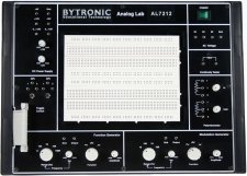
ViewThe AL7212 is designed for experimentation with analogue circuits in the laboratory. The AL7212 is a self-contained trainer which includes a DC regulated and AC power supplies, function generator, modulation generator, continuity tester, potentiometers and toggle switches. The unit is supplied with a breadboard to help students experiment with test circuity using various components without having to solder. A number of ready to use experiment circuit boards are provided.
Experiments:
- Silicon, Zener, LED Diode Characteristics
- Common Base NPN and PNP Transistor Characteristics
- Common Emitter NPN and PNP Transistor Characteristics
- Common Collector NPN and PNP Transistor Characteristics
- N-Channel FET Characteristics
- Common Emitter Amplifier
- Common Collector Amplifier
- Common Base Amplifier
- Zener Voltage Regulator
- Transistor Series Voltage Regulator
- Transistor Shunt Voltage Regulator
- Low Pass – High Pass Active Filters
- Active Band Pass Filter
- Phase Shift Oscillator
- Wien Bridge Oscillator
- Colpitt Oscillator
- Kirchoff’s Laws (KCL and KVL)
- Thévenin’s Theorem, Maximum Power Transfer Theorem
- Reciprocity Theorem, Superposition Theorem
-
ARM Design and Experiment Board
 View
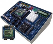
ViewThe ARM9 is an electronics development board with the add-on ARM9 board. ARM is the industry’s leading provider of 32-bit embedded RISC microprocessors, offering a wide range of processors based on a common architecture and delivering high performance together with low power consumption and system cost.
The ARM9 provides a learning platform for this important RISC Microprocessor. With an easy to use operational systems and development process, simply enter commands directly into the CPU.
-
Basic Electricity Trainer
 View
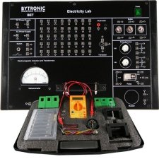
ViewThe basic electricity trainer can be used to develop the student’s abilities and teach basic electrical circuits such as series and parallel circuits, electromagnet induction, coil behaviour with AC and DC circuits, diode and transistor characteristics etc. This simple training kit provides a strong operation for future studies in electrical or electronics.
Experiments:
- Resistances individually, as well as in series and in parallel connections
- Ohm’s law mathematical relationship between three variables; voltage (V), current (I) and resistance (R).
- The behaviour of current when light bulbs are connected in a series/parallel circuit.
- Kirchhoff’s Law for electrical circuits
- R-C circuit and the behaviour of a capacitor in an R-C network and phase shift due to capacitor.
- The L-C circuit and its oscillations
- The characteristics of a semiconductor diode
- The characteristics of a transistor.
- Faraday’s Law of electromagnetic induction
- The behaviour of current when inductance is introduced in the circuit.
- Lenz’s Law and effect of eddy current.
- The relay and constructing a switching circuit by using a relay.
- The Oersted experiment
- The phenomenon of mutual induction.
- Construction and study of the step down transformer with the help of coils and cores.
- Construction and study of the step up transformer.
- The effects of moving I core on a step up transformer
- Conversion of a galvanometer into voltmeter.
- Conversion of a galvanometer into ammeter.
- The Hysteresis curve.
-
CPLD/FPGA Digital Logic Circuit Design Experimental
 View
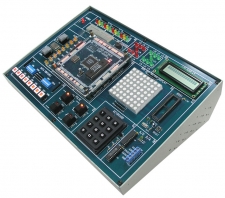
ViewIn today’s environment CPLD (Complex Programmable Logic Devices) and FPGA (Field Programmable Gate Arrays) are the first-choice components for the design of applications in the communication, industrial automation, image processing and extensive engine control areas. To allow users to have an exceptional experimental platform, the CPLD trainer has support for Altera or XILINX chips.
-
Digital Electronics Lab
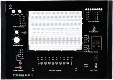 View
ViewThe DL7211 is designed for experimentation with digital circuits. It is a self-contained trainer including DC power supplies, function generator, modulation generator, continuity tester, potentiometers and toggle switches. A breadboard is supplied with the unit to allow easy access for the students to connect and test various components without the hassle of soldering. A number of ready to use experiment circuit boards are available and fourteen boards are provided with the lab.
Experiments Boards:
- Logic Gates: AND, OR, NAND, NOR and EX-OR
- Universal Gate – NAND/NOR Gate: NOT, AND, OR Gate Implementation
- EX-OR Gate Implementation
- Demorgan’s Theorem
- EX-OR Gate Application: Odd and Even Parity Generator, Binary word comparator
- Code Conversion: Binary to Gray and Gray to Binary
- Code Conversion: BCD to Excess-3 Code
- Binary Adder/Subtractor: 2 Bit Binary Half Adder, 3 Bit Binary Full Adder, 2 Bit Binary Half Subtractor, 2 Bit Binary Parallel Adder
- Encoder/Decoder: 8 to 3 Line Encoder, 3 to 8 Line Decoder
- Multiplexer/Demultiplexer: 4 to 1 Line Multiplexer, 1 to 4 Line Demultiplexer
- Flip-Flops: R-S, D, J-K, T Flip-Flops
- Shift Register: 4 Bit Serial In – Parallel Out
- 4 Bit Synchronous Binary Counter: Up Counter
- 4 Bit Binary Ripple Counter: UP/DOWN Counter
-
PCI Interface Design Trainer
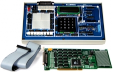 View
ViewThe PCI application is now widely used and has replaced the ISA system. PC-based interfacing and I/O experimentation had been based on the ISA (Industry Standard Architecture) bus, however, the PCI (Peripheral Component Interconnect) bus, makes it much more difficult for users to interface their own circuits directly to the PC. The PCIDT rectifies this situation enabling the experiments to be carried out via the PCI bus.
The PCIDT provides a solution for teaching PC-based interfacing to various I/O devices on modern PCs using the PCI bus. Pre-written experiments cover I/O devices from switches and 7-segment displays and A/D and D/A conversion to the optional DC and stepper motors. A complete introduction to PC interfacing covering PC interfaces and how to connect a range of common I/O devices is provides along with twelve experiments, with their program listings in assembly language and C, based on the PCIDT’s pre-wired circuits. Using the exercises in the textbooks and tools, users are able to learn quickly in controlling I/O under Windows through a PCI interface card. Users can develop and learn PCI I/O control, in addition experiments with C or VB language. The system contains two main units: the interface card and the experiment platform. The design ensures that none of the experiments require soldering. The unit is enclosed in a strong and durable case.
-
Power Electronics Lab
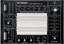 View
ViewThe Power Electronics Lab is used to perform power electronics circuit experiments. Student studying the characteristics of power electronics devices and the applications of power devices will find this an essential piece of equipment. The applications of power devices are in alarm circuit, lamp flasher, rectifiers, choppers, inverters and also commutation circuits.
Experiments:
- The characteristics of SCR
- The characteristics of UJT
- The characteristics of MOSFET
- The characteristics of IGBT
- The characteristics of DIAC
- The characteristics of TRIAC
- The characteristics of PUT
- The class B commutation circuit
- The class C commutation circuit
- The class D commutation circuit
- The class F commutation circuit
- Resistor triggering circuit
- Resistor-Capacitor triggering circuit (half-wave)
- Resistor-Capacitor triggering circuit (full-wave)
- The SCR triggered by UJT
- The SCR triggered by 555IC
- The SCR triggered by Op-Amp 741IC
- Ramp and pedestal triggering circuit using anti-parallel SCR in AC load
- The UJT relaxation oscillator
- The voltage commutated chopper
- The Bedford inverter
- The single phase PWM inverter using MOSFET and IGBT
- The half-wave controlled rectifier with resistive load
- The full wave controlled rectifier (mid-point) with resistive load
- The fully controlled bridge rectifier with load
-
Transducer Trainer
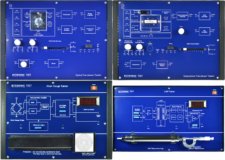 View
ViewThe TRT is a collection of four transducer trainers which include Optical, Temperature, Strain gauge and LVDT. The four different trainers help teach students an introduction into various elements of transducers. The strain gauge trainer uses a cantilever beam arrangement to produce strain on the strain gauge with weights placed on the free end of the cantilever. The seven-segment LED display shows strain in micro strain units. Different weights are provided to perform linearity and sensitivity experiments.
The Optical Transducer comprises of various sensors and transducers which provides the basic knowledge for sensing light and signal conditioning of the signals received from the sensors and transducers. The Temperature Transducer trainer covers four different types of transducers. Experiments covering fundamental characteristics of transducers and the study of transducer controlled switching/alarm systems can be performed.
The LVDT (Linear Variable Differential Transformer) is the most widely used inductive transducer for displacement measurement. LVDT is a secondary transducer which converts the displacement directly into an electrical output proportional to the displacement. The trainers seven-segment LED display shows displacement in mm with a sensitivity of 10mV/mm in the range of 10mm.
Experiments:
Optical Transducer Experiments
- Characteristics of Filament Lamp
- Characteristics of Photovoltaic Cell
- Characteristics of Photoconductive Cell
- Characteristics of PIN Photodiode
- Characteristics of Phototransistor
- Optically Controlled Switching System
Temperature Transducer Experiments
- Characteristics of IC Temperature Sensor
- Characteristics of Platinum RTD
- Characteristics of NTC Thermistor
- Characteristics of NTC Bridge Circuit
- Characteristics of K type Thermocouple
- Temperature controlled Alarm System (1 NTC)
- Temperature controlled Alarm System (2 NTC)
LVDT Transducer Experiments
- Study of Input Output Characteristics of LVDT
- Determination of Linear Range of Operation of LVDT
- Determination of Sensitivity of LVDT
- Measurement of Phase Difference between LVDT Secondary Winding
Strain Gauge Experiments
- Study of Strain Measurement using Strain Gauges and Cantilever Assembly
- Determination of Linear Range of operation of Strain Measurement
- Determination Sensitivity of Trainer