-
Flow Control
 View
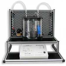
ViewThe PCT-M1 Flow control trainer unit is a self-contained system comprising a pump connected through PVC pipes to a flow sensor, a valve and to a rotameter used to see actual flow rate in the system. The clear tank and pipes allows the student to see the processes they are controlling. The study of flow control and monitoring in a system can be performed through the graphical based software supplied with the unit, which has PID control with graphical interface for data analysis.
The PCT-M1 only requires connection to a PC through a USB connection. The control module is contained on the unit and has a mimic of the systems and LED indication.
Experiments:
- Proportional control
- Proportional and Integral control
- Saturation and integral windup
- Three term or PID control
-
Level Control
 View
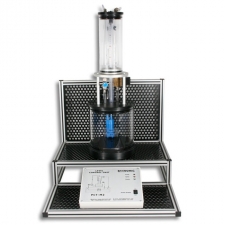
ViewThe PCT-M2 Level control trainer system enables the study of the principles in Level control and monitoring in a system. The system is self-contained and only requires connection to a PC through USB. The control module is contained on the unit and has a mimic of the systems and LED indication. The PCT-M2 can be controlled through the graphical based software supplied with the unit providing PID control.
The system comprises a pump connected through PVC pipes from a reservoir tank to a process tank and a valve to control the flow out of the process tank into the reservoir tank. The level in the process tank is measured using a pressure transducer and a needle type drain valve is fitted to provide a disturbance to the system. The clear tanks and pipes allow the student to see clearly the process they are controlling.
-
Pressure Control
 View
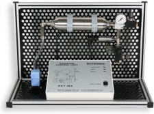
ViewThe PCT-M3 Pressure control trainer system enables the study of the principles in pressure control and monitoring in a pressurised system. The system is self-contained and only requires connection to a PC through a USB. The control module is contained on the unit and has a mimic of the systems and LED indication. The PCT-M3 can be controlled through the graphical based software supplied with the unit providing PID control.
The systems comprises a compressor connected to a reservoir tank, a regulator valve, a pressure sensor, a needle valve to add a disturbance and a pressure gauge to indicate the pressure in the system. The built in compressor provides for a safe working environment and removes the need for connection to an airline or additional compressor.
-
Temperature Control
 View
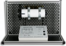
ViewThe PCT-M4 Temperature control trainer system enables the study of the principles in temperature control and monitoring in a system. The system is self-contained and only requires connection to a PC through a USB. The control module is contained on the unit and has a mimic of the systems and LED indication. The PCT-M4 can be controlled through the graphical based software supplied with the unit providing PID control.
The system comprises of a rod that is heated using a thermoelectric element mounted in an enclosed tube, three PRT sensors are fitted along the rod to measure the temperature and a fan is fitted to the end of the tube to provide a disturbance. The tube is made from PTFE and guards are fitted to the fan and the heat sink to provide a safe working environment.
-
Process Control Trainer
 View
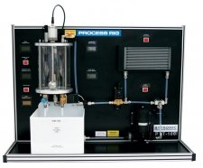
ViewThe PCT-100, Process Control Trainer, is a fully integrated, self-contained bench top apparatus consisting of a Process Module, and a Control Console with a built in power supply. A Windows based software with full control and data acquisition is included. A number of experiments in process control are included covering Flow, Level, Pressure, Temperature.
The PCT-100 control console is easily connected to a PC using the USB connection or to a PLC using D type connectors. The console has a mimic of the process module on the front and includes fault switches, and test points from all of the transducers. Level is measured using a 0 to10v Magnetostrictive sensor; pressure is measured using a Gage 0 to 5bar sensor and Flow using A turbine flow rate sensor. PT1000 are used to measure temperature in both the sump and process tank. A diverter valve can be used to direct the liquid through a forced air-cooling process to cool the liquid in the system. Two proportional valves are used to control flow into and out of the process tank, a manually adjustable needle valve is used to add disturbances to the system and a pressure relief valve fitted for safety.
Data is displayed on the five LCD displays fitted to the process module, and through the software data can be monitored, saved or printed. The software has a PID controller with Supervisory Control and Data Acquisition and trending features.
-
Process Control and Instrumentation
 View
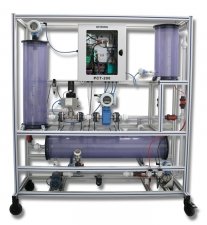
ViewThe PCT-200 Process Control and Instrumentation unit is a fully integrated, fully equipped, self-contained floor standing process control system, representative of industrial process control systems used in many industries such as chemical, oil, food, water, power and other process industries. The PCT-200 is fitted with state-of-the-art intelligent process instruments and actuators networked using Fieldbus technology meeting the requirements for Industry 4.0. The system is available with choice of Fieldbus; PROFIBUS, PROFINET, ETHERNET and others, as required. The unit is supplied with all necessary controllers and software, including PLC, PLC programming software and SCADA software. Siemens and Allen Bradley PLCs are available, and others can be supplied on request.
The PCT-200 can be configured to implement different control strategies for flow and level control using cascade, feed-forward and multi-variable strategies, separate level alarms and process and device temperature monitoring. Control of the system is through SCADA (Supervisory Control and Data Acquisition) software using a PC with an Ethernet connection.
The PCT-200 is fitted with clear tanks, pipes and industrial instruments, actuators and sensors. Labworks cover; Instrument set-up and calibration, actuator elements and characteristics, feedback control systems, fieldbus systems, Ethernet and LAN technology.
Water is pumped around the system using a speed-controlled three-phase pump, controlled by a variable frequency inverter, from a reservoir tank to two process tanks. The pump outflow goes through a venturi-tube providing flow measurement using a differential pressure transmitter. A pressure transmitter is used to measure the discharge pressure from the pump and can be used for experiments on the pump characteristics. Manual ball valves can be set to direct the flow around the system. The level in process tank one can be measured using the differential pressure transmitter, and in process tank two, using the ultrasonic level transmitter. A temperature transmitter is fitted in process tank one for monitoring of the water temperature.
The outlets of process tank one from the reservoir tank goes to process tank two through an electromagnetic flow meter and then to a modulating control valve fitted with a pneumatic positioner. The control valve can be used in conjunction with the flow transmitter for flow control, or in conjunction with the ultrasonic level transmitter for level control in process tank two. A cascade control system can also be implemented by feeding the level controller output as a set-point to the flow controller.
-
PCT-PIDHM
 View
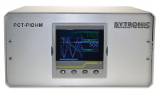
ViewThe recorder/controller offers the ultimate in graphical recording combined with PID control. It has four highly accurate universal inputs for data recording and PID control. This secure data-recording device with accurate control is enhanced by a full colour, ¼ VGA display to bring a crystal clear operator interface. The 3.5 TFT display offers incredibly clear visualisation of process parameters with a wide selection of configurable views to best suit the application. Views include: horizontal and vertical trends; horizontal and vertical bar graphs; numeric; alarm panel, alarm status, and control loops. The unit also provides user wiring from the front of the unit for detailed configuration without the need to connect to a PC.
PID Control Loops functionality includes one of the best auto-tune facilities available along with overshoot inhibition (cutbacks) and also provides remote access to a further 100 programs that can be easily retrieved via FTP or USB memory stick. The recording functionality utilises the secure strategies and UHH format As well as having multiple real-time views and historical data review on the unit, multiple data archiving strategies are provided utilising the 50MB on-board flash memory, removable USB and data transfer via FTP to a specified server.
The four universal input channels provide a high accuracy and 125ms parallel sampling. An additional 30 virtual channels can be utilised to provide maths, counter, slave communications and totalizer functionality within the instrument.
The unit can be used to control the PCT-100 for Flow, Level and Pressure through the “D” connector fitted. PCT-PIDHM if an informative and intuitive control device that allows the student, through its graphical representation, to easily see the control procedure being implemented.
The device has four universal inputs, two digital inputs and three relay outputs.
-
PCT-PIDSM
 View
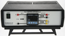
ViewThe PID Controller familiarises students with the operation and principles of an industrial controller using different input signals. The PID controller is a sophisticated auto-tuning PID controller with selectable thermocouple, RTD, voltage or current inputs and two outputs, relay and voltage output. The controller can be configured as one on/off or PID control and up to two alarm outputs, or as two on/off or PID controls (heat/cool) plus alarm output. It has a large dual four digit LED display to show the set point and the process value.
-
PCUSIM
 View
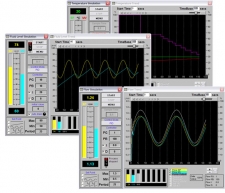
ViewPCUSIM is a simulation software used to teach process control. The program is aimed at further and higher education students learning process engineering and process control using Three Term Control (PID) methods.
PCUSIM has a graphical display of all data in real time. Graphs can be analysed, rewound, saved and printed. Experiments for flow, level, temperature and batch can be performed. Students can perform the same experiments many times with the same initial condition and different control parameters, allowing closer comparisons of outcomes.
For each of the control screens in flow, level, temperature and batch, displays show : start and stop buttons, the control module, the principle variables being measured, PID parameters, set-point; real-time graph with start time and time base, state of current reading and reading being examined with tick boxes for each traces to displayed.
Courseware manual and build in help files provided to allow students to proceed without full time supervision.
-
WinCODAS
 View
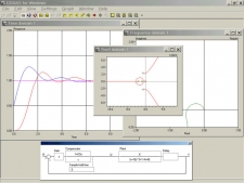
ViewWinCODAS is an application for Control System Design using a Multiple Document Interface (MDI) which allows an arbitrary number of child windows to be created. In each child window the behaviour of a system may be examined in different ways. WinCODAS allows time and frequency responses to be drawn. There is a root domain where root-loci may be plotted either in the s-plane or z-plane.
Nonlinearities may be defined in a flexible and simple manner and their characteristics drawn. These nonlinearities can then be included into the control loop simulation. Time domain responses may be drawn as phase-plane diagrams. A wide range of cost-functions may be defined, settling time, integral of error squared. The cost-functions are evaluated automatically when a response is produced. The frequency domain supports direct and inverse Nyquist diagrams, Bode gain and phase plots and Nichols plots. Closed-loop gain contours (M-contours) may also be drawn. The root domain shows the open-loop poles and zeros of the system and draws root-loci for continuous-time systems with or without transport delay and discrete-time systems. Damping-ratio or Jury contours may be superimposed on a root locus diagram. For rational transfer functions, the positions of all the closed-loop poles may be displayed in a table and marked on the root locus plot.
A digitised cursor is available in all domains to obtain details of data on any plot. The cursor can be switched from absolute to relative mode to allow relative measurements such as peak overshoots or the period of an oscillatory response. There is an auto-scale function and a zoom feature that allows users to magnify any section of a plot. Each child window can have multiple plots; none of which are lost when the window is resized. The system transfer functions are entered in “free-format”. Continuous-time, discrete time and sampled-data systems may be simulated by defining the appropriate transfer function and sample hold time. There are several mapping tools that allow the user to transform transfer functions into explicit z-domain representations including: zero-order hold z-transform, rectangular rule, Tustin’s rule with pre-warping and there are a number of manipulation tools for changing the presentation of the transfer functions into Bode form, pole/zero form. The simulated system is shown graphically in a separate window and its configuration can be different for each child window. As a child window is brought into focus, the system graphic changes dynamically and so the user knows the precise nature of the system being simulated. The general system includes an overall system gain, two transfer functions, a transport delay, two nonlinearities and a zero-order hold. These elements can be included or excluded. There are three possible inputs to the system. In this way the regulation behaviour due to load disturbances and measurement noise can be simulated as well as the performance with more standard set-point or reference inputs.