-
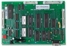
8086 Microcontroller Trainer
 View
ViewThe MIC-8086 Development and Training System includes a target board based on the 16-bit 8086 microprocessor. Designed as a general purpose unit it simplifies the teaching of the 8086 CPU and its commonly used peripherals. Suitable for use at all levels, from simple programs flashing an LED to use as a controller in complex projects. The MIC-8086 is used as a development system for 8086 Assembler Code programs, the EPROM based monitor providing a user interface to a PC through its serial port. Assembler code programs for the 8086 are constructed on the PC and downloaded from the host in Intel Hex format. Programs can be entered into the integral WINDOWS based, LINE-by-LINE assembler, disassembled and easily debugged with the monitoring facilities. LINE assembled programs can also be saved and re-loaded when required.
Standard connectors give full access to Data and Address buses so that logic analysers and other diagnostic equipment can be connected easily for demonstration and debugging purposes. All major components are retained in turned pin I/C sockets this enables faults to be easily applied without fear of damage to the target board for the teaching of fault finding techniques. The teaching of Logic and Signature Analysis and In-Circuit Emulation techniques is enhanced because the board may be set up for a realistic dedicated application
-
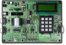
PIC Training Board
 View
ViewThis trainer, based on the PIC24FJ256GB110 16-bit microcontroller has been designed to support the teaching of programming and/or interfacing. The board may be programmed by the user with Microchip’s MPLAB and C30 compiler; the user can then implement the programs in assembly language or C to control the board’s facilities. The program may then be downloaded into the PIC24 (over writing the monitor) using an external programmer.
The PIC24 board can also be controlled using Microsoft Visual Express C++ 2010. The monitor program enables commands from a PC host to control the board through a USB connection. This enables programs to be implemented on a PC to carry out many of the included exercises. A library of C/C++ functions is supplied for Microsoft Visual Express C++ 2010 (similar functions could be written for any compiler/language which has USB communications facilities).
Experiments:
- Read switch values to control LEDs (e.g. speed of rotating pattern)
- Using the RS232 interface to communicate with a PC host running a terminal emulator
- Read keypad and display result on an LCD
- Control heater temperature using PWM by either switching heater or motor (control of PWM may be on/off or combinations of PID)
- Read potentiometer (analogue or digital) to control motor speed using PWM
- Use CANBUS to communicate with another device
- Communicate with a PC host through USB
- Communicate with a USB device such as a flash drive
-
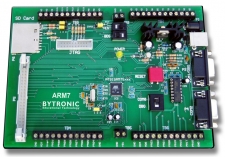
ARM7
 View
ViewThe ARM7TS microcontrollers training system is based around the Atmel® AT91SAM7S range of microcontrollers; a high performance micro-controller with 128K bytes of downloadable non-volatile FLASH EEPROM and 32K bytes of SRAM with high performance 32-bit RISC architecture and a high density 16-bit instruction set with real-time emulation and embedded trace support, which combine micro-controller with embedded high-speed flash memory. The ARM7 family is a range of low-power 32-bit RISC microprocessor cores optimized for cost and power-sensitive consumer applications. The ARM7TS is designed for the introduction of ARM technology in to students
The ARM7TS consists of the ARM7 Microcontroller board fitted with the Atmel AT91SAM7S128, Crossware™ ARM7 “C” Software Development Suite, Jaguar™ JTAG, interface cables, power supply and training manual.
The ARM7 Development Suite includes an advanced optimizing C compiler, Code Creation Wizards, source level instruction and peripheral simulator extendable to simulate complete target systems, source level debugger and the Crossware “Jaguar” JTAG to USB debugger interface. Software downloading to the target is possible by plugging the Jaguar into the JTAG connector on the ARM7 board and into a USB port on a PC. Programs are developed in ‘C’ or “C++”, debugged and then compiled before downloading them. Program download can also be achieved through either the 9 way D type, serial port connection or the USB port.
A 40way IDC is fitted to the board and provides access to the controller ports and can be used for direct connection of additional application equipment. Access to the ports is also available through a screw terminal blocks allowing connection for demonstration or development purposes.