-
PCC2
 View
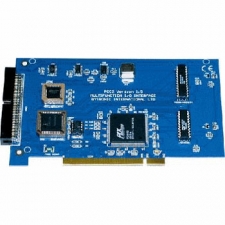
ViewThe PCC2 Internal Digital and Analogue Interface Card is PCI architecture compliant. PCI Cards are dynamically allocated at start-up, rather than being determined in hardware on the card.
The 8255 is a general purpose programmable peripheral interface (PPI). The device has twenty four I/O lines arranged as three ports A, B and C.
- Port A consists of one 8-bit data output latch/buffer and one data input buffer.
- Port B consists of one 8-bit data output latch/buffer and one data input buffer.
- Port C consists of one 8-bit data output latch/buffer and one input buffer. This can be split under mode control into two 4-bit ports.
The 8255 has three main modes of operation, which may be applied to the I/O lines in two groups of twelve. On application of the power, or when the chip is reset, all lines are configured as inputs and must then be initialised to the user’s requirements.
The 8253 is a programmable counter/timer chip with three independent 16-bit Counter Timer Channels (CTCs). Multiple modes are available, programmed in software, and each CTC can be clocked at up to 5MHz. CTCs 0, 1 and 2 are functionally identical and each have two inputs, clock (CLK) and gate (GATE) and one output (OUT). The primary use of CTCs is to generate accurate control cycles that do not require software supervision, especially in non real-time operating system environments. These control cycles typically involve counting, accurate timing or generating output waveforms.
CTCs have a number of applications:
- Programmable Rate Generator
- Event Counter
- Binary Rate Multiplier
- Real Time Clock
- Digital One-Shot
- Complex Motor Controller
The DAC8228 is a dual 8-bit Digital to Analogue Converter generates two voltage outputs in the range 0-5v.
The ADC0848 is an 8-bit successive approximation Analogue to Digital Converter. The in-built eight channel multiplexer can be software configured for single ended, differential or pseudo-differential modes of operation. The maximum throughput time for an 8-bit conversion is 40µs (25khz).
-
PPI2
 View
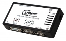
ViewThe Parallel Port Interface (PPI) units provide quick and easy interfacing to the PC by connecting a cable to the parallel port. This method of connection reduces the initial set-up time, eliminates the requirement to open up the PC and increases the flexibility of the unit by enabling it to be moved easily between PCs.
The PPI2 Version has integral relays and is designed for the control of 24v systems and includes one analogue 8-bit 0-5v input, making this a very versatile interface that has many applications. A feature of the PPI2 is its coloured LED’s that provide the student and teacher with a visual monitor of the I/O status. The 12 opto-isolated inputs and 8 relay outputs of the PPI2 are accessible through 15 way ‘D’ type connectors and the single 0 to 5V analogue input through a 9 way ‘D’ type connector. The Parallel Port Interfaces have been designed so that they can be used with almost any programming language, for example, Visual BASIC, Delphi and C and also National Instruments LabVIEW. Also included are drivers and sample programs.
-
PPI1
 View
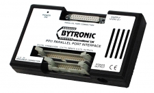
ViewThe Parallel Port Interface (PPI) units provide quick and easy interfacing to the PC by connecting a cable to the parallel port. This method of connection reduces the initial set-up time, eliminates the requirement to open up the PC and increases the flexibility of the unit by enabling it to be moved easily between PCs. This provides a quick and easy method of connecting TTL devices to a PC. The PPI1 is designed for interfacing with TTL 5v devices and includes one analogue 8-bit 0-5v input. The Parallel Port Interfaces have been designed so that they can be used with almost any programming language, for example, Visual BASIC, Delphi and C and also National Instruments LabVIEW. Also included are drivers and sample programs.
-
USB Interface Card
 View
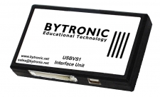
ViewThe USB interface enables a PC to control target devices such as the multi-applications board, bead sorter, washing machine simulator or CST through a USB. Signals from the 8255 and 8254 devices are taken to a 40 way header (compatible with the 40-way connector on the other Bytronic products).
The USB interface uses the HID (Human Interface Device, the built in HID driver which is part of the operating system) protocol to communicate with the host PC removing the requirement for a specific device driver. The IO transfer is approximately a 64byte packet every millisecond sufficient for target devices such as the multi-applications board.
A Windows DLL is available to enable control from Visual Studio C++, C#, VB.Net. A number of sample Visual Studio C++, C# and VB.Net projects are provided enabling users to develop their own programs.• 8255 general purpose programmable peripheral interface (PPI). The device has twenty four I/O lines arranged as three ports A,B and C. Port A consists of one of 8-bit data output latch/buffer and one data input buffer. Port B consists of one of 8-bit data output latch/buffer and one data input buffer. Port C consists of one 8-bit data output latch/buffer and one input buffer. This can be split under mode control into two 4-bit ports.
• 8254 programmable counter/timer chip with three independent 16-bit Counter Timer Channels (CTCs). Multiple modes are available, programmed in software, and each CTC can be clocked at up to 5 MHz. CTCs 0, 1 and 2 are functionally identical and each have two inputs, clock (CLK) and gate (GATE) and one output (OUT).