-
Electro-Pneumatic Training Panel
 View
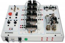
ViewThe Electro-Pneumatic Training Panel is a compact and comprehensive training panel comprising cylinders, valves, both electrical and electro-pneumatic, that are easily connected through 4mm colour coded terminals and 4mm pneumatic quick action terminations, this makes the EPTP is an ideal introduction to Electro-Pneumatics. The student can study single and double acting cylinders using various types of valves. The EPTP comprises power supply, On/Off switch with indicator light; emergency stop; two-way selector switch; 5/3 monostable valves, 5/2 monostable valve, 5/2 flip flop Valve, 5/3 open centre valve, 5/3 closed centre valve, flow regulators, single acting cylinder, double acting cylinder and .magnetic reed switches
Courseware covers a general introduction to the EPTP, the electrical and pneumatic connection, the characteristics and use of the various types of valves, the characteristics of the cylinders, how they can be connected to the valves, using a PLC to control the system. The coursework is supplemented by technical documentation.
-
ASi- Technology Trainer
 View
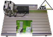
ViewThe ASi-T module is designed to allow the theory and practice of the Actuator Sensor Interface to be taught. The module uses a combination of practical applications and the theory. The use of automation, improved methods of control and the development of Fieldbus technology are all essential learning requirements for an engineer.
The use of AS-i intelligent sensors, actuators and remote I/O in the most efficient and effective way and how to integrate AS-i into higher Fieldbus systems are included in the course. Students will build, configure and exercise their own AS-interface system from the beginning and the planning and installation of Fieldbus networks. No previous knowledge of AS-i or other Fieldbus systems is required.
The ASi-T module consists of a Siemens Simatic S7-300 Modular PLC complete with AS-i master, and all required I/O. The ASi-T is mounted on an aluminium board, and is supplied with a courseware manual.
Experiments:
- Practical Exercise, AS-i system 3 – Siemens Master
- Siemens STEP 7- Micro/Win 32 software
- Exercising slave I/O
- Executing AS-i functions
- Reading slave ID codes
- Obtaining slave I/O codes
- Hand-held test tool
- Automatic addressing
- Profiles and Parameters
- The intelligent Sensor Health bit
-
Automated Production System
 View
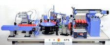
ViewThe Automation Production System is comprised of modules with varying functions that are electrically and mechanically linked, and when combined simulate an actual industrial process such as material dispensing, sorting of products, processing, and storing. The APS is designed to enables students to acquire knowledge of automation and production systems using PLC programming with the aid of sensors and actuators in the area of mechatronics.
The APS is constructed on an aluminium frame and can be mounted on a bench or supplied with a support stand. The APS has an operating console with on/off switches, emergency stop switch and PLC control with the I/O connections, electrical and pneumatic.
The functionally of the APS is to allow students to study the automation process and to understand how to control various modules to ensure they work together. The APS uses a bottling plant as the process with containers being placed onto the conveyor belt. The presence/absences of a container is detected using sensors and if present the containers are moved to the linear conveyor system. The linear conveyor moves each container onto the two axis pick and place module where the pneumatic gripper of the transfer unit picks up the container and places it onto the indexing rotary table. The motorised rotary module will index the container through to the volumetric filling modules where the container is filled. The container is then capped at the capping module and the containers are transferred from the rotary module to the weighing module. Once weighing is complete the XY palletising module will store the finished item in the pallet section.
The process allows the control of production using a series of modules that are independently controlled and require the modules to be synchronised for the operation to be performed successfully and is representative of a full-size production system.
-
Batch Processing Unit
 View
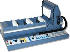
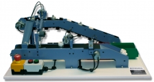
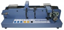
ViewThe Batch Process Trainer (BPT) represents the mechanics and control requirements of; electroplating, printed circuit board etching, paint stripping and degreasing as used in sequential processing industries.
The BPT consists of a transporter that traverses left and right over five separate process tanks with eight flight bar locations. A lift bar, attached to the transporter is used to raise and lower flight bars in and out of the process. The first program would implement only a few simple movements but the exercises become more complex until the student is capable of programming the carriage movements required for a complete (simulated) electroplating process. Solutions to the various exercises are also provided.
The control panel has LEDS for indication of the sensor activities. Manual control is available using the switches and a joystick. Connection through colour coded 4mm shrouded sockets on the front panel. PLCs can be connected using the 24vd.c. ’D’ type connectors and a PC can be connected, using a suitable interface, through the IDC on the rear of the unit.
Experiments:
Exercises for the BPT using a PC
- Sensors, actuators and hard interlocks
- Software installation and software program
- Simple control program
- Simple square dance
- General sequence
- Time-Out detection
- Transporter initialisation
- Flight bar detection and relocation
- Assignments
Exercises for the BPT using a PLC
- Sensors, actuators and hard interlocks
- Soft interlocks
- Semi automatic operation
- Simple square dance
- General sequence
- Time-Out detection
- Initial flight bar position detection
- Flight bar detection and relocation
-
Five Axis Robot Arm
 View
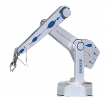
ViewThe 5ARA is a complete self-contained five axis vertically articulated robot arm system designed for bench top automation. The hand terminates in a mounting plate for grippers, and comes standard with electric gripper fitted. The 5ARA uses light weight, high efficiency digital motors driving through steel reinforced polyurethane timing belts and the compact micro-stepping drives providing both speed and precise control. The 5ARA includes the simple to use controller with fast CPU and DSP processors an incremental optical encoders and an intuitive teach pad. The 5ARA is, fast, accurate and reliable and has a 500mm reach. It is easy to program and is capable of the most complex tasks. The Software makes getting started easy with the programming of the robot, from very simple tasks to the most complex motions, being quickly and easily programmed. Interfaces and peripherals may be programmed, assisted by project manager software in one Windows screen. The Arm comprises two limbs 250mm each plus 360 degrees base rotation, therefore, the workspace is a sphere 1000mm diameter.
The encoders on the 5ARA are miniature optical incremental encoders fitted to each axis and act as watchdogs. The loop is closed after completion of each individual motion, which is not the same as servo control. Without encoders the 5ARA will run accurately and indefinitely open loop without error because of the micro-stepping drives and accurate transmission. If the robot has a collision, the controller will not know and will continue with the program, and the robot could be out of position. Such collisions usually only occur accidentally due to programming error, and it would then be necessary to run the calibration routine after such a collision. A software solution is provided for quick calibration using the encoder to accurately read back the position of the robot when de-energized. The robot can be positioned by hand and its position updated by pressing a key on the keypad. The kinematics software then computes the exact X-Y-Z position of the robot with the hand pitch and roll in degrees.
-
Industrial Control Technology – ICT3
 View
ViewThe Industrial Control Technology (ICT3) is a representation of an industrial assembly system that allows the study of control methods used in product assembly and inspection in a manufacturing process. Various industrial sensors and the methods, in which they can be used, are studied. The Sensors and actuators are used to sort components, assemble them and test for correct assembly followed by acceptance or rejection. The unit can be controlled from a PLC using the 24v dc I/O interface.
The unit assembles two components a plastic ring and an aluminium peg. A chain conveyor processes the components through the sort area; the plastic rings and aluminium pegs proceed down a ring and peg chute and are then assembled on the belt conveyor. At the assembly check area components are inspected for correct assembly and when the components reach the final area, if correctly assembled they proceed to the acceptance area, faulty assemblies are rejected into a reject bin. Correct programming of the controller (PLC) must be achieved to ensure incorrect components are not sent to the final assembly area.
Once the program has been written and the system is working correctly, various faults can be applied using the fault insertions switches, providing diagnostic solving issues. LED’s on the sensors provide a visual indication of the operational status of the sensors. The sort and reject solenoids are fitted with sensors to monitor the operation of the solenoids and to ensure the operation has been correctly performed
Experiments
- Sorting routine
- Closed loop solenoid control
- Queue counting
- Operation timing
- Plastic ring detection/rejection
- Metal peg detection/rejection
- Component acceptance and rejection
- Component queue handling
- Complete system control
- Start / Stop switches
-
Industrial Control Technology – ICT4
 View
ViewThe Industrial Control Technology unit (ICT4) is a representation of an industrial assembly system that allows the study of control methods used in product assembly and inspection as in a manufacturing process. Industrial sensors of various types are used and the methods, in which they can be applied are studied. The Sensors and actuators are used to sort components, assemble them and test for correct assembly followed by acceptance or rejection. The unit can be controlled from a PLC using the 24v dc on board connections or from a PC thru the USB on board connection.
The unit assembles two components a plastic ring and an aluminium peg. A chain conveyor processes the components through the sort area; the plastic rings and aluminium pegs proceed down a ring and peg chute and are then assembled on the belt conveyor. At the assembly check area components are inspected for correct assembly and when the components reach the final area, if correctly assembled they proceed to the acceptance area, faulty assemblies are rejected into a reject bin. Correct programming of the controller (PLC or PC) must be achieved to ensure scrap components are not sent to the final assembly area.
Once the program has been written and the system is working correctly, various faults can be applied using the fault insertions switches, providing diagnostic solving issues. LEDs on the sensors provide a visual indication of the operational status of the sensors. The sort and reject solenoids are fitted with sensors to monitor the operation of the solenoids and to ensure the operation has been correctly performed.
Sample I/O code for ©Microsoft VB.NET, C#.NET, and ©Delphi are supplied and additional code is available from the FTDI website: www.ftdichip.com/Support/SoftwareExamples/CodeExamples.htm for the users to write their own program. The ICT4 can also be controlled using LADSIM4.
-
LADSIM
 View
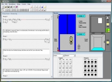
ViewLADSIM is a fully functional ladder logic design and PLC simulation software program that incorporates the functions used in PLC ladder programming. LADSIM uses the PC as a virtual PLC.
LADSIM includes a visual editing environment for graphical programming. A simple ‘drag and drop’ method is used to add functions to the ladder rung, and comments can be added to each rung for documentation purposes. LADSIM functions include inputs, outputs, timers, counters, flags and shift registers. An interactive debugger is included allowing the program to be tested before being used to control a specific application.
LADSIM has eight internal simulations; Annunciator, Traffic Light, Car Park, Elevator, Drinks Machine, Packing Line, Bottling Plant, and the ICT3. Each simulation is designed to aid and test knowledge of programming in ladder logic.
LADSIM has the ability to be connected to external devices, through a suitable interface. The student can start with the internal simulations and then move onto the ICT3 simulation once completed it is then possible to connect an actual ICT3, using an interface card and control this through the real I/O. The courseware begins with a general introduction to PLCs, the various programming methods available and the fundamentals of ladder logic programming and then moves onto the functions of LADSIM. Developing programs to monitor and control each of the simulations is part of the curriculum coverage.
-
Rotary Transfer Unit
 View
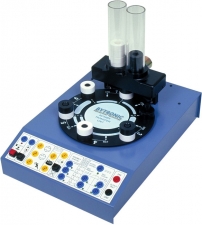
ViewThe Rotary Transfer Unit (RTU) represents industrial indexing, manufacturing and assembly processes. A number of programming exercises are possible from simple control operations to fault-tolerant processes.
The RTU consists of a component dispensing mechanism positioned above a turntable. A turntable with metal pegs represents the assembly station that can be rotated in a clockwise or anti-clockwise direction with a two speed control. Using a control signal it is possible to dispense and assemble black and white rings from the clear plastic tubes onto the pegs in various combinations.
Each station is identified using a binary code method with black and white sections on the underside of the turntable; this is also represented on the top of the turntable to help understand binary identification methods. Four infra-red reflective sensors identify the position and station number using a bi-colour identification system. The dispensing mechanism, using, infra-red sensors, identifies if the peg has a ring or rings loaded and the colour of the rings.
The control panel includes an on /off and emergency stop push button and a button to silence the internal buzzer. Four switches are fitted on the rear of the unit for fault insertion. The unit can be controlled by a PLC, having ten digital inputs and six digital outputs, through the D type sub connectors on the rear, or the 4mm colour coded shrouded sockets on the front of the control panel. Connection can also be made to a PC, using a suitable interface card, or Microprocessor training board, through the IDC header with TTL connection. Control is implemented using high or low level programming languages.
Experiments:
- Movement of rotary table
- Initialisation
- Station counting
- Dispensing
- A production line system
- Follow a set routine
-
Single Conveyor Unit
 View
ViewThe Single Conveyor Unit (SCU) has been designed as a representation of a conveyor system used in the manufacturing process to allow the study of control methods used at an introductory level. The unit is based around a common application found in industry of sorting items as they travel along a conveyor system.
The unit consists of a belt conveyor driven by a 24V d.c motor with sensors and an actuator situated along its length. Two different sized metal boxes are placed in turn at the start of the conveyor and as the box travels along the conveyor it enters an area consisting of two sensors that determines the length of the box. At the end of the conveyor is a sorting area with a sensor and linear solenoid. In the sorting area, the sensor detects the box and through the program controlling the single conveyor, the box is either accepted and allowed to continue or rejected, and ejected by the solenoid.
Connection to a PLC is through two 24V d.c D type connectors and 24V d.c 4mm colour coded shrouded sockets. The PC can be connected using a suitable interface card connected to a 26-way IDC connector with TTL.
Experiments:
- Belt conveyor control
- Rejecting A Box
- Sorting boxes
- Time-out error detection