-
Control System Trainer
 View
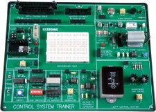
ViewThe Control System Trainer (CST) is designed for the study of digital and analogue control engineering using fundamental control theory with simple direct connections or the use of programming software. The CST can be used to carry out the various experiments using the elements and breadboard to design a control application to a specification. Simple or complex experiments are possible by linking the range of devices and sensors on the CST.
The CST has two main project areas and a range of digital logic building blocks with a prototyping area. The first project area has a D.C. motor, for speed and direction control combined with a heater for temperature control. Consisting of a 5V dc motor; this is used in a closed-loop to drive a fan that cools a heater to a set temperature or can be used to break an infra-red beam for speed control. The second, main project area is a light control system; a controller is required to maintain a set luminance when an external interference from a second lamp is introduced, it uses two light sources, one source of light and one source of light disturbance.
There are a variety of projects to undertake using the range of sensors and devices on the CST. These elements are a bread board area, voltage to frequency converter, light dependant resistor (LDR), a de-bounced switch, a tilt switch, Piezo buzzer, TTL monitor, a bank of logic switches, a logic probe and a clock source. Headers that accept standard solid core wires are used to connect each element of the CST. Connection to a PC is possible using a suitable interface card through digital and analogue connections.
Experiments:
- Generic courseware for the CST
- Generate digital outputs
- Read in digital inputs
- Read in digital inputs on port B and output them on port A
- Sound Piezo buzzer when CST is tilted
- Pulse an output at a rate specified by user
- Sense closure of the de-bounced switch and keep a count of the occurrences
- Sense closure of the de-bounced switch and keep a count of the occurrences over a specified time interval
- Count input pulses from the clock generator, via a timer/counter channel
- Implement software generated PWM signal
- Implement hardware generated PWM signal using two timer/counter channels and clock generator
- Implement hardware generated PWM signal using two timer/counter channels and user input
- Generate an analogue voltage in the range 0-5V
- Read an analogue voltage in the range 0-5V
- Generate triangular wave output
- Calibrate the LDR circuit in the light control box
-
Magnetic Levitation System
 View
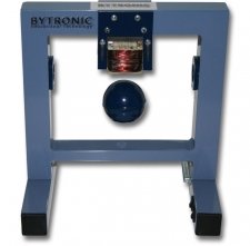
ViewThe Magnetic Levitation System (MLS) is a classic control problem used in many practical applications such as transportation, magnetic levitated trains, using both analogue and digital solutions to maintain a metallic ball in an electromagnetic field. The MLS is a single Degree of Freedom system for teaching of control systems; signal analysis, using real-time control applications such as MATLAB.
The MLS is a nonlinear, open-loop unstable and time varying dynamical system. The basic principle of MLS operation is to apply the voltage to an electromagnet to keep a ferromagnetic object levitated. The object position is determined through a sensor. Additionally the coil current is measured to explore identification and multi loop or nonlinear control strategies.
-
Modular Servo Workshop
 View
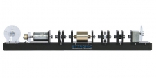
ViewThe Modular Servo Workshop (MSW) system has been designed for the study and practical application of basic and advanced control methods. These included typical variable factors such as friction, damping and inertia and a number of position/speed control methods ranging from PID to LQ and time-optimal control. The flexible design of the MLS allows the configuration of a system to be modified to suit user requirements.
The MSW has an integrated environment for the analysis of digital servo control problems and synthesis of control algorithms. The system comprises several hardware units, and software. The DC motor module can be coupled with several other modules by timing belts. A number of linear and nonlinear mechanical modules have been designed to show the influence of backslash, damping, elasticity and friction. The units may be studied individually before completing the system. The linear damping module consists of a paramagnetic disc which runs between the poles of the permanent magnet. The inertia module contains a solid metal roll. The encoder module is used to measure the rotational angle. A steel base plate provides firm fixing to the modules, enabling imitation of block schematic diagrams, however, all electrical connections are performed inside the software.
The system can be classified as multivariable (SIMO) with two measurable states and one control variable.
The MSW operates with a PC based digital controller that communicates with the position sensor and motor by an I/O board. The I/O board is controlled by the real-time software which operates with MATLAB/Simulink. A comprehensive range of experiments may be carried out using Modular Servo and associated software.
-
Multi Application Board
 View
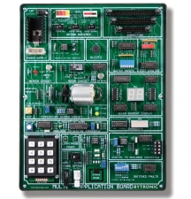
ViewThe Multi Applications Board (MAB) contains a variety of experiments on one board and is ideal for learning how to interface a PC or Microcontroller to applications. The techniques of controlling data transmission, keyboard entry, digital sound production, D.C. motors, heaters, and visual displays can be controlled using a PC with a programming language, the MAB can also be used as target for a microcontroller. This involve the fundamentals of microprocessor or computer programming, such as decision making, D to A and A to D conversion, open and closed loop control, creating delay loops, using subroutines and event counting.
The MAB Primary components are: a 12V d.c. motor, this is used for closed-loop control to drive a fan which cools a heater/resistor to a set temperature. Several other elements are on the MAB these include a Piezo buzzer, TTL monitor, a bank of logic switches, a logic probe power point, a strain gauge and amplifier, a bar-graph and a seven segment display, switched faults and a potentiometer that can be used as an analogue input.
Experiments:
- Switched inputs
- Control of an output port
- Use of the Analogue to Digital Converter
- Use of the temperature sensor
- Digital to Analogue Converter
- Control of the buzzer frequency
- Driving the seven segment display unit
- Keypad scanning
- Pulse Width Modulation control of the DC motor unit
- Closed loop control of the DC motor unit
-
Pendulum Control System
 View
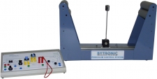
ViewThe Pendulum Control System, PCS2, is designed for the study of control engineering and theory. The PCS2 consists of a carriage module and analogue control module with a mimic of the system. It can function as a stand-alone analogue system or be interfaced to an external controller such as a PC using a suitable interface card. The PCS2 is supplied with an interface card and PCSDS software. The software includes attempted Linear control, attempted Harmonic control, and Direct Digital Control and Fuzzy Logic control. Students can compare the performance of the different controllers. Connection is through 4mm-shrouded colour coded sockets and to an interface card through the IDC connection.
The PCS2 can be used in two different modes, an inverted pendulum or an overhead crane, each mode presents a control situation that requires a separate approach and solution and an understanding of how feedback systems function. The first mode; control of an inherently unstable system, to balance the pendulum in the inverted position the pivot must be continuously moved to correct the falling pendulum. In the second mode; the carriage module is turned upside down to act as a crane, the pendulum swings into an equilibrium position with the centre of mass below the pivot, control the Linear position of the load, with very oscillatory dynamics.
Experiments:
- Static and dynamic characteristics of the pendulum control system
- Analogue control of an inverted pendulum
- Fuzzy Logic control of the inverted pendulum
- Direct Digital controller design and implementation: inverted pendulum
- Direct Digital controller design and implementation: swinging crane
-
Sorter Unit
 View
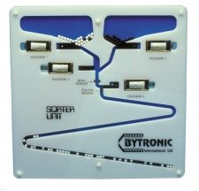
ViewThe Sorter Unit (SRU) is designed to be used as a control application from PC or microcontroller. The SRU includes the use of opto-electronic sensors for counting and sorting and control of linear solenoid actuators.
The SR is a two dimensional bead sorting and counting system that has two distinct functions. It is a three-layer sandwich construction, which encapsulates fifty white beads, and fifty black beads, which are free to move around a pattern of hoppers with tracks cut into the middle layer.
Bead Pattern Creation: The unit has two hoppers to store two different coloured beads. Two linear electrical solenoids are used to open and close gates at the outlets of the hoppers. If either solenoid is briefly de-energised, a bead of the appropriate colour is released from the hopper and rolls down the zigzag track that has a number of possible bead patterns in the track. Feedback from an infrared through-beam sensor is used to ascertain if a bead has been successfully dispensed each time.
Bead Sorting: When both hoppers are empty and the required bead pattern has been achieved the unit may be turned upside down to allow the beads to be sorted back into their respective hoppers. A second pair of solenoids are used to deflect each coloured bead into a hopper and an infrared reflective sensor is used to determine the colour of each bead.
The sensor’s output sends a binary signal to the computer to signify black or white depending upon how much of the infrared beam is reflected from the bead. An audible indicator on the SRU is used to indicate ‘end of sequence’ or that an error has occurred.
A PC fitted with a suitable internal interface card can be used to connect to the SRU through the IDC header and Programing software used to write a control programs for the Unit. A microprocessor can also be used for control.
Experiments:
- Producing a program for control of the sorter unit
- The bead sensor
- The buzzer
- A program to generate a bead sequence
- A program to sort the beads out
-
Stepper Motor Training System
 View
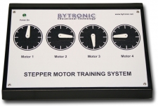
ViewThe Stepper Motor Training System (SMTS) is a self-contained unit that connects to a PC through USB. The SMTS is designed to teach the principles and operations of stepper motors and can be used as an application for programming, providing experience into the many applications of stepping motors.
Stepping motors, are motors which rotate one step when supplied with a pulse. Typical applications include CNC machine tool drives, X-Y plotters and Printers. The control signals required are almost always the same, regardless of motor size.
The system comprises of four Stepper Motors and includes an interactive software program. The software introduces the principles of stepper motors, their use and control. The software includes questions and answers to allow the teacher to evaluate the knowledge of the students.
-
Traffic Control Unit
 View
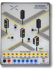
ViewThe Traffic Control Unit (TCU) can be used as an application for control from either PLC or PC. For PLC control a PLC with six digital inputs and eleven digital outputs is required to control all features on the unit. For PC control a USB is fitted, allowing control from either the supplied software or programing software compatible with the USB interface.
The TCU represents a typical crossroads junction controlled by two pairs of traffic lights together with a pedestrian crossing on one approach. The TCU features a clear mimic of a traffic junction with the lights and pedestrian crossings represented by LED’s in the appropriate colours. Four buttons are used to simulate vehicle sensors built into the surface of the road and represent traffic flow. Further buttons are used to control the pedestrian crossing and a reset signal.
The Acrylic front cover protects the electronics and the mimic from damage. The TCU is supplied with a manual that includes a user guide, courseware suggestions and solutions to the exercises.
USB or IDC connection supplied as required.
Experiments:
- Basic traffic light sequence
- Dual traffic light sequence
- Traffic counting
- Time alteration according to traffic flow
- Pedestrian crossing (stand alone)
- Complete system control
- Adjusted pedestrian priority
-
Twin Rotor Mimo System
 View
ViewThe Twin Rotor MIMO System (TRMS) behaviour resembles that of a helicopter. From the control point of view it illustrates a high order nonlinear system with significant cross-couplings. A mathematical model design of TRMS needs knowledge of aero dynamical physical laws. The TRMS system has been designed to operate with a PC-based digital controller that communicates with the position, speed sensors and motors by a dedicated I/O. The I/O board is controlled by the real-time software which operates in the MATLAB / Simulink RTW/RTWT environment.
The TRMS consists of a beam pivoted on its base so that it can rotate freely both in the horizontal and vertical planes. At both ends of the beam there are rotors driven by DC motors. A counterbalance arm with a weight at its end is fixed to the beam at the pivot. The state of the beam is described by four process variables: horizontal and vertical angles measured by encoders fitted at the pivot, and two corresponding angular velocities.
Two additional state variables are the angular velocities of the rotors, measured by speed sensors coupled with the driving DC motors. In a real helicopter the aerodynamic force is controlled by changing the angle of attack. In the TRMS the angle of attack is fixed. The aerodynamic force is controlled by varying the speed of rotors. Significant cross-couplings are observed between actions of the rotors. Each rotor influences both position angles. A design of stabilising controllers for TRMS is based on decoupling.
-
Washing Machine Simulator
 View
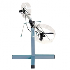
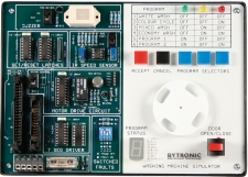
ViewThe Washing Machine Simulator (WMS) is an application for electronic control engineering. The unit incorporates a series of input and output devices, which together simulate the actions of a typical domestic washing machine. The WMS has two main areas. The first area comprises the electronic circuits and connector sockets, the second area is the indicators, a motorised disc (which represents the washing machine drum) and the user controls. The circuit board incorporates test points, a fuse and four switches for fault insertion.
Three blue push buttons are used to select a ‘wash program’ from the software program and inputs from these buttons turn on green, yellow and red LED’s. The binary pattern displayed may be compared to a ‘program selector table’ to indicate the current choice of program. A grey push button is used to cancel the current choice and a red push button to ‘accept’ input for the controller. A mechanically latched push button with a built in LED provides an input, which simulates the open/closed status of the washing machine door. An infra-red reflective sensor mounted beneath the disc supplies feedback on the speed of the motor. A seven-segment display is used to highlight the ‘wash program status’. The status options are: Empty, Fill, Heat, Wash, Rinse, Spin, Dry and Complete.
Motor speed can be controlled using PWM and a buzzer activated to indicate the end of the ‘wash program’ (can be enabled or disabled using on-board switch). The buzzer can also be used to indicate that the ‘door’ has been opened or that a fault has occurred. Variations for programming the WMS are possible using two switches that change the input/output characteristics of the motor drive and speed sensor feedback. The WMS can be connected to a PC, using a suitable interface, or to a microcontroller.
Experiments:
- Control of digital outputs
- Control of the seven segment display
- Reading the program selector switches
- On/Off control of the DC motor
- Controlling the DC motor/speed open loop
- Reading the motor speed feedback
- Colour wash program cycle
- Closed loop control of the DC motor