-
Advanced Fibre Optic
 View
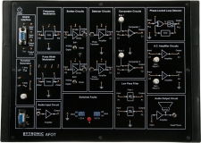
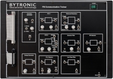
ViewThe Bytronic AFOT Fibre Optic Communication trainer provides a full duplex method of transmitting information from one place to another by sending pulses of light through an optical fibre, the light forms an electromagnetic wave that is modulated to carry information. The advanced fibre optics communication trainer is designed to learn the communication techniques in Fibre Optics.
The trainer demonstrates properties of Fibre Optics Transmitter and Receiver, characteristics of Fibre Optic cable, different types of Modulation/Demodulation techniques via fibre link. It can also be used to demonstrate various digital communication techniques.
Experiments:
- Fibre optic analogue link
- Fibre optic digital link
- Intensity modulation technique using an analogue input signal
- Intensity modulation technique using a digital input signal
- AM system using analogue and digital inputs
- FM and PWM modulation systems
- Propagation loss in optical fibre
- Bending loss in optical fibre
- Measurement of numerical aperture
- Characteristics of E-O converter (LED)
- Characteristics of F.O communication link
- Measurement of power using optical power meter
- Characteristics of E-O converter using optical power meter
- Propagation loss using optical power meter
- Setting of fibre optic voice link using intensity modulation, AM-FM and PWM
- Study of switched fault in AM-FM and PWM systems
- Full duplex computer communication using RS232 ports and software
- BIT rate measurement
- Determining the density of the fibre optic link
- Determination of power margin (power budget)
-
Analogue Communications Lab
 View
ViewThe Analogue Communications Lab are a collection of self contained boards that can be used together to form a comprehensive series of digital experiments and provide the requirements for gaining an understanding of digital communications. The boards have built in power supplies, test points, switched faults, inputs, outputs and functional blocks.
7501 – DSB/SSB AM Transmitter Datasheet (PDF)
7502 – DSB/SSB AM Receiver Datasheet (PDF)
7503 – Frequency Modulation/Demodulation Datasheet (PDF)
7504 – FM Communication Datasheet (PDF)
7505 – Noise Audio/Amplifier Datasheet (PDF)
7507 – Four Channel Analogue TDM Datasheet (PDF)
7511 – Frequency Division Multiplexer/Demultiplexer Datasheet (PDF)
7408 – Audio Input Module Datasheet (PDF) -
Antenna Trainer System
 View
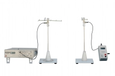
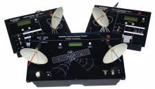
ViewThe Antenna Trainer System is ideal for introducing the principles of Antenna operations and design. The ATS7261 training system includes a set of modular mechanical elements forming various antennas, a transmitter unit and a detector unit. The Antenna Training System comes with a motorised antenna unit that allows for the automated recording of radiation patterns of the antennas. This operation is normally performed by rotating the transmitting antenna at different angles by hand and measuring the radiated intensity.
The motorised antenna unit consists of a microcontroller based system for capturing, displaying and printing of the antenna radiation patterns. The system captures a signal at an interval of ten rotations driven by a stepper motor and the radiation pattern is then displayed on the PC.
Experiments
- Arranging the trainer and performing functional checks
- Perform a modulation and demodulation test
- Plotting the polar graph/radiation pattern of an antenna manually
- Plotting a polar graph/radiation pattern of an antenna using the software
- Simple dipole l/2, l/4 and 3l/2 antenna
- Folded dipole l/2 antenna
- Yagi-UDA 5 and 7 element simple dipole antenna
- Yagi -UDA 3, and 5 element folded dipole antenna
- Hertz antenna
- Zeppelin antenna
- l/2 Phase array (end fire) antenna
- l/ 4 Phase array (end fire) antenna
- Combined co-linear and Broad side array antenna
- Log periodic antenna
- Cut paraboloid reflector antenna
- Loop, Rhombus, Ground plane, Slot and Helix antenna
- Perform polarisation test
- Variation in the radiation strength at a given distance from the antenna
- Reciprocity theorem for antennas
- Matching stub
- SWR measurement
- Antenna current sensor
-
Audio Input Module
 View
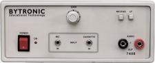
ViewThe 7408 audio input module allows speech and music signals as audio input to any communication trainer, it sends these signals over different communication systems. The audio input module accepts the input signal from either a microphone or a cassette recorder which it amplifies by a gain adjustable voltage amplifier. The audio input module and audio output module in conjunction with the trainer allows the user to study the effect of different communication system on transmission and reception of speech and music. The trainer can be used in applications requiring conversion of sound signals to electrical signals.
-
Audio Output Module
 View
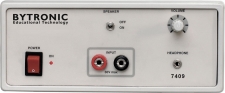
ViewThe 7409 audio output module has been specifically designed for the use with Bytronic communication trainers. This module can be used with any of Bytronic communication receivers to convert the audible frequency electric signals to audible output. The audio output module 7409 in conjunction with audio input module 7408 and other Bytronic communication trainers allows the user to study the effects of speech and music.
-
Basic Fibre Optic
 View
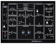
ViewThe BFOT is designed to teach the basics of Fibre Optics. The unit demonstrates properties of Fibre Optics transmitter and receiver, characteristics of Fibre Optic cables and different modulation/demodulation techniques. A number of experiments are included in the workbook and the BFOT can also be used to demonstrate various digital communication techniques via Fibre Optic link using the range of digital communications trainers.
Experiments:
- Fibre optic analogue link
- Fibre optic digital link
- The relationship between the input signal and received signal in a 650nm fibre optic analogue/digital link
- AM system using analogue and digital inputs
- FM and PWM modulation systems
- Propagation loss in optical fibre
- Bending loss in optical fibre
- Measurement of numerical aperture
- Characteristics of E-O converter (LED)
- Characteristics of fibre optic communications link
- Measurement of power using optical power meter
- Characteristics of E-O converter using optical power meter
- Propagation loss using optical power meter
- Setting of fibre optic voice link using AM-FM and PWM
- Study of switched fault in AM-FM and PWM systems
- Determination of the bit rate supported by the fibre optic link
- Determination of the sensitivity of the fibre optic link
- Determination of power margins (Power budget)
- V-I characteristics of photo LED
- Characteristics of photo detector
- Measurement of bit error rate
-
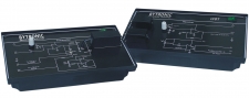
Data Formatting and Carrier Modulation Transmitter
 View
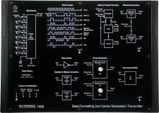
ViewThe 7406 data formatting and carrier modulation transmitter trainer is a digital communication system which efficiently explains all communication processing steps involved in digital transmission and reception of analogue signals. Various digital modulation techniques such as ASK, FSK, PSK, DPSK, QPSK etc can be implemented using combinations of the 7406 and 7407 trainers.
In order for this unit to work correctly the 7407 carrier demodulation and data reformatting receiver is required.
Experiments:
- Data formats
- Amplitude shift keying
- Frequency shift keying
- Phase shift keying
- Differential phase shift keying
- Quadrature phase shift keying
- Differential quadrature phase shift keying
-
Data Reformatting and Carrier Demodulation Receiver
 View
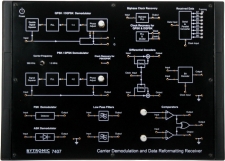
ViewThe unit is one of a range of digital communication trainers and provides all necessary inputs and connections for students. The 7407 carrier demodulation and data reformatting receiver trainer is a digital communication system which efficiently explains all communication processing steps involved in digital transmission and reception of analogue signals. Various digital modulation techniques such as ASK, FSK, PSK, DPSK, QPSK etc can be implemented using combinations of the 7406 and 7407 trainers.
In order for this unit to work correctly the 7406 data formatting and carrier modulation transmitter trainer is required.
Experiments:
- Data formats
- Amplitude shift keying
- Frequency shift keying
- Phase shift keying
- Differential phase shift keying
- Quadrature phase shift keying
- Differential quadrature phase shift keying
-
Delta, Adaptive Delta and Delta Sigma Modulation/Demodulation
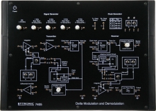 View
ViewThe unit is one of a range of digital communication trainers and provides all necessary inputs and connections for students to study Delta, Adaptive Delta and Delta Sigma Modulation Demodulation. The 7405 covers the concepts of delta modulation demodulation, slope overloading, adaptive delta modulation demodulation, sigma delta modulation demodulation and amplitude overloading.
Experiments:
- Study of delta modulation & demodulation
- Study of adaptive delta modulation & demodulation
- Study of delta sigma modulation & demodulation
-
Digital Communications Lab
 View
ViewThe Digital Communications Lab are a collection of self contained boards that can be used together to form a comprehensive series of digital experiments and provide the requirements for gaining an understanding of digital communications. The boards have built in power supplies, test points, switched faults, inputs, outputs and functional blocks.
7401 – Sampling and Reconstruction Datasheet (PDF)
7402 – Pulse Amplitude Modulation/Demodulation Datasheet (PDF)
7403 – TDM Pulse Code Modulation Transmitter Datasheet (PDF)
7404 – TDM Pulse Code Modulation Receiver Datasheet (PDF)
7405 – Delta, Adaptive Delta and Delta Sigma Modulation/Demodulation Datasheet (PDF)
7406 – Data Formatting and Carrier Modulation Transmitter Datasheet (PDF)
7407 – Data Reformatting and Carrier Demodulation Datasheet (PDF)
7408 – Audio Input Module Datasheet (PDF)
7409 – Audio Output Module Datasheet (PDF)
7410 – PAM-PPM-PWM Modulation and Demodulation Datasheet (PDF)
7411 – 8-Bit Binary Data Generator Datasheet (PDF) -
DSB/SSB AM Receiver
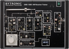 View
ViewThe 7502 DSB/SSB AM receiver trainer is part of an analogue communication range which provides all the necessary inputs, test points and connections for experimentation. The 7502 trainer teaches students the basics of DSB/SSB Amplitude modulation and transmission systems through measurement of voltages via the on-board test points.
The 7501 DSB/SSB AM Transmitter is required to work with this unit.
Experiments
Automatic Gain Control:
- Double Sideband AM Generation
- To calculate modulation index of DSB wave by trapezoidal pattern
- Double Sideband AM Reception
- Study of Diode Detector
Single Side Band Transmission:
- Signal Sideband AM Generation
- Single Sideband AM Reception.
- Operation of the Automatic Gain Control Circuit (AGC)
Receiver Characteristics (Selectivity, Sensitivity, Fidelity):
- To plot selectivity curve for radio receiver
- To plot sensitivity curve for radio receiver
- To plot fidelity curve for radio receiver
-
DSB/SSB AM Transmitter
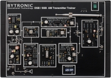 View
ViewThe 7501 DSB/SSB AM transmitter trainer is part of an analogue communication range which provides all the necessary inputs, test points and connections for experimentation. The 7501 trainer teaches students the basics of DSB/SSB Amplitude modulation and transmission systems through measurement of voltages via the on-board test points.
The 7502 DSB/SSB AM Receiver is required to work with this unit.
Experiments
Automatic Gain Control:
- Double Sideband AM Generation
- To calculate modulation index of DSB wave by trapezoidal pattern
- Double Sideband AM Reception
- Study of Diode Detector
Single Side Band Transmission:
- Signal Sideband AM Generation
- Single Sideband AM Reception.
- Operation of the Automatic Gain Control Circuit (AGC)
Receiver Characteristics (Selectivity, Sensitivity, Fidelity):
- To plot selectivity curve for radio receiver
- To plot sensitivity curve for radio receiver
- To plot fidelity curve for radio receiver
-
FM Communication
 View
ViewThe 7504 FM Communication trainer is part of an analogue communication range which provides all the necessary inputs, test points and connections for experimentation. The 7504 trainer teaches students the principles of FM communications through observation of waveforms via various on board test points.
Experiments
- Frequency deviation and modulation index
- Marker insertion to evaluate frequency deviation
- Spectrum of the FM signal
- Study phase locked loop detector
-
Frequency Modulation/Demodulation
 View
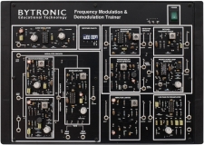
ViewThe 7503 Frequency Modulation and Demodulation trainer is part of an analogue communication range which provides all necessary inputs, test points and connections for experimentation. The 7503 trainer provides the students with an introduction into frequency modulation/demodulation and various experiments can be performed to teach the students the process of FM generation and detection. The students will interact with the trainer by observing the waveforms and signals via various on board test points.
Experiments
- Frequency Modulation using Varactor Modulator
- Frequency Modulation using Reactance Modulator
- Operation of Detuned Resonant Circuit
- Operation of Quadrature Detector
- Operation of Phase-Locked Loop Detector
- Operation of Foster – Seeley Detector
- Operation of Ratio Detector
-
Frequency Division Multiplexer/Demultiplexer
 View
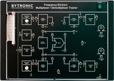
ViewThe 7511 Frequency Division Multiplexer/Demultiplexer trainer is part of an analogue communication range which provides all the necessary inputs, test points and connections for experimentation. The 7511 demonstrates FDM techniques by transmitting a single communication line through two different modulated inputs.
-
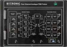
Four Channel Analogue
ViewThe 7507 four channel analogue TDM trainer is part of an analogue communication range which provides all the necessary inputs, test points and connections for experimentation. The 7507 is a practical trainer for students to study time division multiplexing, amplitude modulation, demodulation, multiplexing and demultiplexing techniques.
-
GPS Trainer
 View
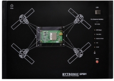
View“Global Positioning System” (GPS) technology is rapidly changing how people find their way around, with GPS navigation becoming more common. The “GPS Trainer” will provide a basic understanding of the GPS fundamentals and satellite design aspects of GPS receivers by connecting to the Satellite with the GPS Antenna.
Experiments
- Understanding the Concept of GPS
- Establishing a Link between the GPS Satellites and the GPS Trainer
- Measurement of Latitude & Longitude
- Effect of DOP
- Study of HDOP & VDOP
- Analysis of NMEA 0183 Protocols
- Analysis of Elevation; Azimuth, SNR
- Study of PRN code
- Study of Common NMEA Sentence Protocol like, GPGGA, GPGLL, GPGSA, GPGSV, GPRMC, GPVTG
- Study of other GPS NMEA Sentences like, GPALM, GPGRS, GPGST, GPMSS, GPZDA
-
Laser Fibre Optic Trainer
 View
ViewThe Laser fibre optic trainer is part of our communication range, the LFOT teaches students the principles of Laser diodes, optical fibres and optical communication. Students can use the LFOT trainer to transmit via optical cables or free space while enabling the student to observe the output signals. The unit teaches the students the concepts of laser technology in an easy and practical way.
Experiments:
- Characteristics of laser diodes
- Study of ACC and APC modes of operation
- Design and evaluation of a laser diode linear intensity modulation system
- Transmission of Laser through an optical fibre
- Laser Free Space Communication
- Determination of Numerical Aperture of Optical fibres
-
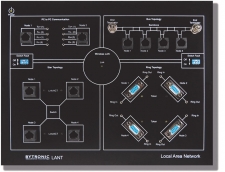
Local Area Network Trainer
 View
ViewThe Local Area Network Trainer provides the student with an understanding of the fundamentals of networking. Student gain a knowledge of the different network layers, cable design and the building of complete networks used in computing. The student can understand and implement various topologies using different IEEE standards. Connections can be made in different topologies and data can be transferred. Topics covered include the protocols and topologies used in networking, measurement of error rate, throughput and the effect of errors on protocols. The versatile software provided with the LANT will allow the student to observe the various effects and configurations on network along with the graphical representation.
Experiments:
- Addressing in TCP/IP
- PING Command
- Implementation of cable designs in Networking
- Implementation of PC to PC with IEEE 802.3
- Implementation of Peer to Peer Network
- Implementation of Client- Server Network
- Implementation of Star topology using 100Base Tx
- Implementation of Bus topology using 10Base2
- Implementation of Ring topology using DB9
- CSMA/CD (Carrier Sense Multiple Access with Collision Detection)
- Token Ring Protocol
- Token Bus Protocol
- Flow Control
- Socket Programming
- Wireless LAN
-
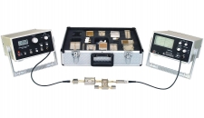
Microwave Intergrated Circuit Trainer
 View
ViewThe MTT7208 Micro-strip Microwave Trainer with Microwave Integrated Circuits (MIC) includes instruments and accessories for studying the characteristics of any MIC component over the frequency range 2.2 to 3 GHz.
The Trainer teaches the characteristics of all components listed below, by measurements of transmission loss and reflection loss. Theory, background of the components and experiments are provided in the teaching manual.
Experiments:
- PC to PC Data Communication using MIC components
- Measurement of transmission loss and reflection loss
- Measurement of substrate dielectric constant using ring resonator
- Measurement of power division, isolation and return loss characteristics
- Measurement of coupling, isolation and return loss characteristics
- Measurement of coupling and directivity
- Measurement of Low Pass filter characteristics
- Measurement of Band Pass filter characteristics
- Measurement of Band Stop filter characteristics
- Measurement of characteristics of Patch antennas
- Measurement of characteristics of an MIC amplifier
-
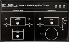
Noise Audio-Amplifier
 View
ViewThe 7505 Noise Audio amplifier is part of an analogue communication range which provides all the necessary inputs, test points and connections for experimentation. The 7505 trainer teaches the students the principles of noise interference in electronics and communications. The students can use the audio amplifier to increase the signal noise to observe the effects via the on board load speaker.
Experiments
- Examine the operation of a noise generator
- Examine the operation of a signal attenuation network
- Measurement of the power output
- Measurement of frequency response
- Analysis of distortion with square wave
- Measurement of noise figure
-
PAM-PPM-PWM Modulation/Demodulation
 View
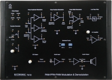
ViewThe Bytronic 7410 PAM-PPM-PWM pulse modulation/demodulation trainer can be used to study Sampling, Pulse Modulation, Demodulation and Signal reconstruction processes. Separate circuits are provided for each technique.
Experiments:
- Pulse Amplitude Modulation using natural and flat top sampling
- PAM using sample and hold sampling
- Pulse Amplitude Modulation and Demodulation with sample, sample and hold and flat top
- PPM using DC input
- PPM using sine wave input
- PPM demodulation
- PWM using different sampling frequency
- Pulse Width Demodulation
- Voice link using Pulse Amplitude Modulation
- Voice link using Pulse Position Modulation
-
Pulse Code Modulation Receiver
 View
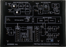
ViewThe 7404 is one of a range of digital communication trainers and provides all necessary inputs and connections for students to study decoding and demultiplexing of data transmitted by model 7403, the pulse code modulation transmitter. On-Board PLL provides regeneration of clock. Synchronization between transmitter and receiver is provided by pseudo random code.
Experiments:
- Study of pulse code modulation
- Study of A/D conversion
- Study of control signals and their timing
- Study of time division multiplexing
- Study of synchronization by pseudo random code
- Study of error check codes
- Three modes of operation to regenerate original signal
-
Pulse Code Modulation Transmitter
 View
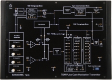
ViewThe 7403 is one of a range of digital communication trainers and provides all necessary inputs and connections for students to study pulse code modulation transmission techniques. A communication link can be established by using model 7404, the pulse code modulation receiver.
Experiments:
- Study of pulse code modulation
- Study of A/D conversion
- Study of control signals and their timing
- Study of time division multiplexing
- Study of synchronization by pseudo random code
- Study of error check codes
- Three modes of operation to regenerate original signal
-
Pulse Amplitude Modulation/Demodulation
 View
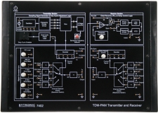
ViewThe unit is one of a range of digital communication trainers and provides all necessary inputs and connections for students to study pulse amplitude modulation / demodulation techniques, time division multiplexing and demultiplexing of signals and signal reconstruction.
Experiments:
- Study of pulse amplitude modulation technique
- Study of time division multiplexing and demultiplexing
- Study of PLL as frequency multiplier to generate clock from sync signal
- Study of effect of varying duty cycle of sampling pulse on signal reconstruction
- Study of 3 modes of operation to regenerate original signal
- 3 connections between transmitter and receiver (clock, sync & information)
- 2 connections (sync & information). Clock regenerated at receiver
- 1 connection (information only). Clock and sync derived at receiver
-
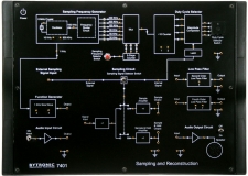
Sampling and Reconstruction Trainer
ViewThe unit is one of a range of digital communication trainers and provides all necessary inputs and connections for students to study signal sampling and reconstruction techniques.
Experiments:
- Sampling and reconstruction of signal.
- The effect of II order and IV order low pass filter on reconstructed signal.
- The effect of sample amplifier and sample and hold amplifier on reconstructed signal.
- The Nyquist criteria for sampling and reconstruction of signal.
- The effect of sample /hold circuit on reconstructed signal
- Effect of sampling pulse duty cycle on the reconstructed signal in sample and sample hold output.
- Comparison responses of 2nd order and 4th order LPFs.
- Verification sampling and reconstruction data transmission scheme for
-
Satellite Communication Trainer
 View
ViewThe Satellite Communication Trainer 7272 provides an in-depth study of a basic satellite communication system. It consists of an Uplink Transmitter, Satellite Link and Downlink Receiver, which can be conveniently placed in the laboratory. The satellite can be placed at an elevated position if required. The satellite transponder receives signals from an Uplink Transmitter and retransmits at different frequencies to a Downlink Receiver. The Uplink and Downlink frequencies are selectable and carry three signals – Video, Audio, Voice and Data simultaneously. Any broadband signal, digital/analogue data or function generator waveforms can be communicated through the Satellite link.
Experiments:
- Understanding the concepts of satellite communication
- Establish a direct communication link between Uplink Transmitter and Down link Receiver using tone signal
- To setup an active satellite link and demonstrate link fail operations
- To establish an audio-video transmission through a Satellite link
- Study base-band analogue signal (voice) in satellite link
- Transmission and reception function generator waveforms through satellite link
- Transmission tone through satellite link
- Establish PC to PC communication using satellite Communication Link
-
Telephone Trainer System
 View
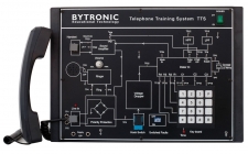
ViewThe Telephone Training System (TTS) helps students to understand the basic concept and functional working of a Telephone system. An onboard mimic is provided that details the various blocks of a telephone and all components. Test points and LED’s are provided to allow students to observe various signals which helps them to understand the working of each block
-
Transmission Line Trainer
 View
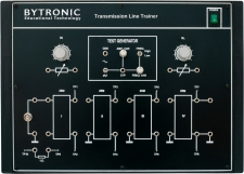
ViewIn telecommunications transmission lines are used to convey signals from one point to another. The line properties become very important especially in multi-channel systems. The TLT is a unique design for experimenting with various properties of a transmission line. The unit provides the basic concepts of a coaxial line and includes all devices and accessories required to conduct the experiments.
Experiments:
- Measuring the Characteristics of a Line
- Measuring the Input Impedance of the Line
- Measuring the Attenuation of a Line
- Phase Displacement between the Current and voltage at input of a Line
- Frequency characteristic of the Line
- Stationary Waves
- Signal Phase Shift along the Line
- Fault Localization within the Line
- Line under Pulsed condition
-
Mobile Phone Trainer
 View
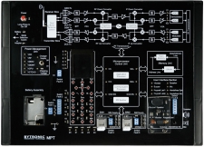
ViewThe Mobile Phone Trainer provides basic theory and working fundamentals of a 2G handset based on one of the most popular handsets, the Nokia 3310/3315. The MPT provides network, power supply, charging and user interface circuits for the detailed block study
Experiments
- To study and measure frequency band
- To study and measure the GMSK signals such as Tx I /Q, Rx I /Q
- To study and observe the system CLK
- Observation of Audio signal
- To study and measure the Power supply
- Study of charging phenomena with fault insertion
- Study and measure PWM signal of Ul circuit such as Vibrator, LED, Buzzer
- Measurement of LCD with fault insertion
- Keypad study with fault insertion
- Observe and measure of the SIM Card CLK with fault insertion
-
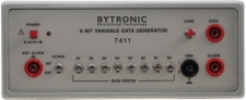
8-Bit Binary Data Generator
 View
ViewThe 7411 can be used with the 7406 and the 7407 as a data input generator. The 7411 can also used as an 8-bit variable TTL data generator independently. The 7411 can produce an external clock (TTL) up to 1MHz that is available from at the clock out socket on the front of the unit. Normally it operates on an internal 240KHz clock.